|
IECM 13.1 User Manual > Modules Included with the IECM > Pulverized Coal (PC) Plant > GET RESULTS > Base Plant > 2. Air Preheater > Air Preheater Diagram |
|
The Air Preheater Diagram result screen shows the major flows into and out of the air preheater:
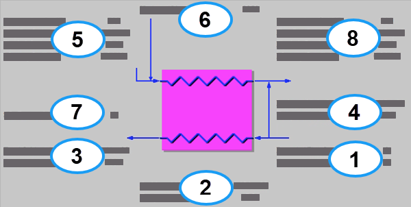
PC: GET RESULTS: Base Plant: 2. Air Preheater: Air Preheater Diagram
Each result is described briefly below in flow order:
•Area 1: Recycled Flue Gas Entering Preheater: Flue gas can be recycled back into the boiler when an O2-CO2 Recycle configuration is specified in Configure Plant. This is more commonly known as an oxyfuel configuration. Flue gas is not recycled in any other configuration.
•Recycled Flue Gas: Volumetric flow rate of the recycled flue gas entering the induced-draft fan.
•Temperature: Temperature of the recycled flue gas entering the induced-draft fan.
•Area 2: Atmospheric Air Entering Preheater
•Ambient Air: Volumetric flow rate of air entering the induced-draft fan, based on the atmospheric air temperature and atmospheric pressure.
•Temperature: Temperature of the atmospheric air entering the induced-draft fan.
•Area 3: Heated Air Exiting Preheater
•Total Oxidant: Volumetric flow rate of the combustion air or recycled flue gas exiting the air preheater, based on the combustion air temperature and atmospheric pressure.
•Temperature: Heated combustion air or recycled flue gas temperature exiting the air preheater. This is a complicated function of the heat content and temperatures of the flue gas.
•Area 4: Leakage Air
•Leakage Air: Volumetric flow rate of the atmospheric air leaking across the air preheater into the flue gas. This is based on the leakage temperature and atmospheric pressure.
•Temperature: Temperature of the atmospheric air leaking across the air preheater into the flue gas. This is determined by the leakage parameter on the base plant performance input screen.
•Area 5: Flue Gas Entering Preheater
•Temperature In: Temperature of the flue gas entering the air preheater. This is determined by the flue gas outlet temperature of the module upstream of the air preheater (e.g., the boiler economizer).
•Flue Gas In: Volumetric flow rate of the flue gas entering the air preheater, based on the flue gas inlet temperature and atmospheric pressure.
•Fly Ash In: Total solids mass flow rate in the flue gas entering the air preheater. This is determined by the solids exiting the module upstream of the air preheater (e.g., the boiler economizer).
•Mercury In: Total mass of mercury entering the air preheater in the flue gas. The value is a sum of all the forms of mercury (elemental, oxidized, and particulate).
•Area 6: Hydrated Lime
•Hydrated Lime In: Total mass of hydrated lime entering the air preheater. Hydrated lime is injected for flue gas treatment at the inlet of the air preheater to remove SO3.
•Area 7: Air Preheater Performance
•SO3 Removal: Percent of the SO3 removed from the flue gas.
•Area 8: Cooled Flue Gas Exiting Preheater
•Temperature Out: Temperature of the flue gas exiting the air preheater. This is determined by the parameter on the Base Plant Performance input screen.
•Flue Gas Out: Volumetric flow rate of the flue gas exiting the air preheater, based on the flue gas exit temperature and atmospheric pressure.
•Fly Ash Out: Total solids mass flow rate in the flue gas exiting the air preheater. This is a function of the percent ash entering the flue gas (furnace emissions input parameter) and the ash content of the fuel.
•Mercury Out: Total mass of mercury exiting the air preheater in the flue gas. The value is a sum of all the forms of mercury (elemental, oxidized, and particulate).
Copyright © 2022-2026 University of Wyoming. All rights reserved. Visit us at https://www.iecm-online.com/