|
IECM 13.1 User Manual > Modules Included with the IECM > Pulverized Coal (PC) Plant > GET RESULTS > NOx Control > 2. Hot-Side SCR > Hot-Side SCR Diagram |
|
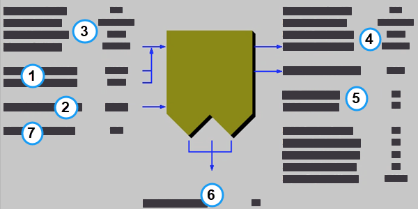
The Hot-Side SCR Diagram result screen shows the major flows into and out of the Hot-Side SCR NOx technology:
PC: GET RESULTS: NOx Control: Hot-Side SCR: Hot-Side SCR Diagram
The following values are displayed:
•Area 1: Reagent:
•Ammonia Inj.: The total mass flow rate of ammonia injected into the SCR. This is a function of the NOx concentration in the flue gas and the ammonia stoichiometric performance input value.
•Steam for Inj.: The total mass flow rate of steam into the SCR. This is the amount of steam added to the SCR to vaporize and transport ammonia into the inlet gas stream. This is determined by the steam to ammonia ratio input value and the ammonia injection.
•Area 2: Catalyst:
•Steam for Soot: This is the amount of steam blown into the hot-side SCR to remove soot buildup on the catalyst layers. The soot blowing steam is assumed to be directly proportional to catalyst volume.
•Initial Catalyst Layers: This is the number of initial active catalyst layers. Three layers are installed initially. It is used to calculate the total pressure drop across the SCR and the auxiliary power requirements. This is set by the input parameter on the Performance parameter screen .
•Reserve Catalyst Layers: This is the number of reserve or extra catalyst layers. These are available for later catalyst additions. It is used to calculate the total pressure drop across the SCR and the auxiliary power requirements. This is set by the input parameter on the Performance parameter screen .
•Dummy Catalyst Layers: This is the number of dummy catalyst layers. A dummy layer corrects the flow distribution. It is used to calculate the total pressure drop across the SCR and the auxiliary power requirements. This is set by the set by the input parameter on the Performance parameter screen .
•Active Catalyst Layers: This is the number of initial active catalyst layers. Three layers are installed initially. It is used to calculate the total pressure drop across the SCR and the auxiliary power requirements. It is equal to the number of initial and reserve catalyst layers.
•Layers Replaced Yearly: Average catalyst layer replacement rate per year. This assumes that all catalyst layers are of equal depth.
•Area 3: Flue Gas Entering SCR:
•Temperature In: Temperature of the flue gas entering the SCR. This is determined by the flue gas outlet temperature of the module upstream of the SCR (e.g., the boiler economizer)
•Flue Gas In: Volumetric flow rate of flue gas entering the SCR, based on the flue gas temperature entering the SCR and atmospheric pressure.
•Fly Ash In: Total solids mass flow rate in the flue gas entering the SCR. This is determined by the solids exiting from the module upstream of the SCR (e.g., the boiler economizer).
•Mercury In: Total mass of mercury entering the hot-side SCR in the flue gas. The value is a sum of all the forms of mercury (elemental, oxidized, and particulate).
•Area 4: Flue Gas Exiting SCR:
•Temperature Out: Temperature of the flue gas exiting the SCR. The model currently does not alter this temperature through the SCR.
•Flue Gas Out: Volumetric flow rate of the flue gas exiting the SCR, based on the flue gas temperature exiting the SCR and atmospheric pressure.
•Fly Ash Out: Total solids mass flow rate in the flue gas exiting the SCR. This is a function of the ash removal parameter on the SCR performance input screen.
•Mercury Out: Total mass of mercury exiting the hot-side SCR in the flue gas. The value is a sum of all the forms of mercury (elemental, oxidized, and particulate).
•Ammonia Slip: Total mass flow rate of ammonia that is unreacted and exits the SCR in the flue gas stream. This is a function if the ammonia injection flow rate, NOx concentration in the flue gas, and NOx removal efficiency.
•Area 5: SCR Performance:
•NOx Removal: Actual removal efficiency of NOx in the SCR. This is a function of the minimum (50%) and maximum removal efficiencies and the emission constraint for NOx . It is possible that the SCR may over or under-comply with the emission constraint.
•TSP Removal: Actual particulate removal efficiency in the SCR. This is set by the input parameter on the Performance parameter screen .
•Area 6: Collected Solids:
•Dry Solids: Total solids mass flow rate of solids removed from the SCR. This is a function of the solids content in the flue gas and the particulate removal efficiency of the SCR.
•Area 7: Wash Water:
•Wash Water: The ammonia that deposits in the air preheater is periodically removed by washing.
Copyright © 2022-2026 University of Wyoming. All rights reserved. Visit us at https://www.iecm-online.com/