|
IECM 13.1 User Manual > Modules Included with the IECM > Pulverized Coal (PC) Plant > GET RESULTS > Mercury > Activated Carbon Injection Diagram |
|
The Activated Carbon Injection Diagram result screen shows the major flows into and out of the water and carbon injection systems:
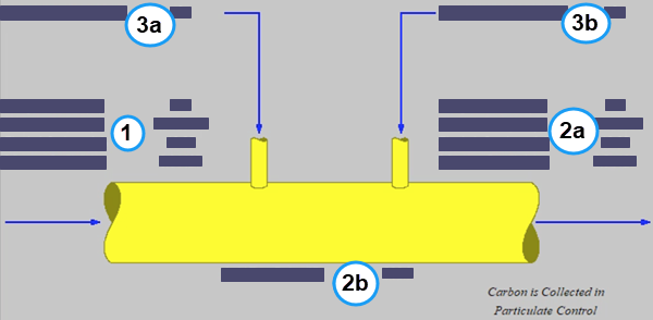
PC: GET RESULTS: Mercury: Activated Carbon Injection Diagram
Each result is described briefly below in flow order:
•Area 1: Flue Gas Prior to Injection:
•Temperature In: Temperature of the flue gas prior to flue gas conditioning.
•Flue Gas In: Volumetric flow rate of the flue gas prior to flue gas conditioning, based on the temperature prior to flue gas conditioning and atmospheric pressure.
•Fly Ash In: Total solids mass flow rate in the flue gas prior to flue gas conditioning. This includes ash, unburned carbon and unburned sulfur.
•Mercury In: Total mass of mercury in the flue gas prior to flue gas conditioning. The value is a sum of all the forms of mercury (elemental, oxidized, and particulate).
•Area 2: Flue Gas After Injection:
•2a:
•Temperature Out: Temperature of the flue gas after flue gas conditioning. This should be above the acid dew point temperature at the bottom of the screen.
•Flue Gas Out: Volumetric flow rate of the flue gas after flue gas conditioning, based on the temperature after flue gas conditioning and atmospheric pressure.
•Fly Ash Out: Total solids mass flow rate in the flue gas after flue gas conditioning. This includes ash, unburned carbon, activated carbon, and unburned sulfur.
•Mercury Out: Total mass of mercury in the flue gas after flue gas conditioning. The value is a sum of all the forms of mercury (elemental, oxidized, and particulate).
•2b:
•Acid Dew Point: This is the temperature that H2SO4 vapor condenses into the liquid phase.
•Area 3: Flue Gas Conditioning:
•3a:
•Water Injected: Water added to the flue gas to reduce the temperature No water is injected if water injection is not specified in the configuration or the inlet temperature is within the approach to saturation relative to the acid dew point.
•3b:
•Carbon Injected: Total activated carbon mass flow rate injected into the flue gas.
|
Note: |
|
Carbon injected into the flue gas is collected downstream in the particulate control device (e.g., the cold-side ESP). |
Copyright © 2022-2026 University of Wyoming. All rights reserved. Visit us at https://www.iecm-online.com/