|
IECM 13.1 User Manual > Modules Included with the IECM > Pulverized Coal (PC) Plant > GET RESULTS > SO2 Control > Wet FGD > Wet FGD Diagram |
|
The Wet FGD Diagram result screen shows the major flows into and out of the Wet FGD SO2 control technology:
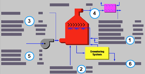
PC: GET RESULTS: SO2 Control: Wet FGD Diagram
Each result is described briefly below:
•Area 1: Reagent:
•Dry Reagent: The total mass flow rate of lime, limestone or limestone with dibasic acid injected into the scrubber. This is a function of the SO2 Removal Efficiency, the Reagent Purity and the Reagent Stoichiometry (all performance input parameters ).
•Makeup Water: Water needed to replace the evaporated water in the reagent sluice circulation stream.
•Area 2: Oxidation:
•Oxidation Air: This is the amount of air used for oxidation.
•Oxidation H2O: This is the amount of water used for oxidation.
•Area 3: Flue Gas Entering FGD:
•Temperature In: Temperature of the flue gas entering the scrubber. This is determined by the flue gas outlet temperature of the module upstream of the scrubber (e.g., a particulate removal technology).
•Flue Gas In: Volumetric flow rate of flue gas entering the scrubber, based on the flue gas temperature entering the scrubber and atmospheric pressure.
•Fly Ash In: Total solids mass flow rate in the flue gas entering the scrubber. This is determined by the solids exiting from the module upstream of the scrubber (e.g., a particulate removal technology).
•Mercury In: Total mass of mercury entering the scrubber. The value is a sum of all the forms of mercury (elemental, oxidized, and particulate).
•Temperature: Temperature of the flue gas entering the scrubber after the forced draft fan. This is determined by the flue gas inlet temperature of the FGD and the Temperature Rise Across ID Fan performance parameter .
•Area 4: Flue Gas Exiting FGD:
•Temperature: Temperature of the flue gas immediately on exiting the scrubber, prior to any flue gas bypass remixing and prior to reheating.
•Temperature Out: Temperature of the flue gas exiting the scrubber. This is a function of flue gas bypass, saturation temperature, reheater and the flue gas component concentrations.
•Flue Gas Out: Volumetric flow rate of the flue gas exiting the scrubber after the reheater, based on the flue gas temperature exiting the scrubber and atmospheric pressure.
•Fly Ash Out: Total solids mass flow rate in the flue gas exiting the scrubber after the reheater. This is a function of the Particulate Removal Efficiency and Flue Gas Bypass parameters.
•Mercury Out: Total mass of mercury exiting the scrubber after the reheater. The value is a sum of all the forms of mercury (elemental, oxidized, and particulate).
•Area 5: FGD Performance:
•Ash Removal: Actual particulate removal efficiency in the scrubber. This is set by the scrubber Particulate Removal Efficiency performance parameter .
•SO2 Removal: Actual removal efficiency of SO2 in the scrubber. This is a function of the maximum removal efficiency (scrubber performance parameter) and the emission constraint for SO2 (emission constraints input parameter ). It is possible that the scrubber may over or under-comply with the emission constraint.
•SO3 Removal: Percent of SO3 in the flue gas removed from the scrubber. The SO3 is assumed to combine with H2O and leave with the ash solids or sluice water as a sulfate (in the form of H2SO4).
•Mercury Removal: Percent of the total mercury removed from the scrubber. The value reflects a weighted average based on the particular species of mercury present (elemental, oxidized, and particulate).
•Area 6: Collected Solids:
•Wet FGD Solids: Total solids mass flow rate of solids removed from the scrubber. This is a function of the solids content in the flue gas and the Particulate Removal Efficiency of the scrubber. The solids are shown on a wet basis.
Copyright © 2022-2026 University of Wyoming. All rights reserved. Visit us at https://www.iecm-online.com/