|
IECM 13.1 User Manual > Modules Included with the IECM > Pulverized Coal (PC) Plant > GET RESULTS > CO2 Capture, Transport & Storage > 1. Ammonia System > Ammonia System Diagram |
|
The Ammonia System Diagram result screen shows the major flows into and out of the ammonia CO2 control system in PC and NGCC plants:
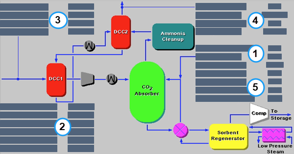
PC: GET RESULTS: CO2 Control: 1. Ammonia System: Ammonia System Diagram
The following values are shown:
•Area 1: Reagent:
•Lean Solv. Flow: This is the lean solvent circulation flow rate.
•Ammonia: This is the makeup solvent.
•Water: This is the water used to dilute the makeup solvent.
•Area 2: DCC:
•Makeup Water: This is the amount of makeup water required.
•Reclaimer Waste: Total solids mass flow rate of solids removed from the ammonia scrubber.
•Cooling Water: This is the total cooling water required for the ammonia system.
•Chilled Water: This is the amount of chilled water required for all of the chillers in the ammonia system.
•Bleed Water: This is the amount of bleed water.
•Refrig. Req.: This is the amount of refrigeration required for all of the chillers in the ammonia system.
•Area 3: Flue Gas Entering Ammonia System:
•Temperature In: Temperature of the flue gas entering the ammonia system.
•Flue Gas In: Volumetric flow rate of flue gas entering the ammonia system.
•Fly Ash In: Total solids mass flow rate in the flue gas entering the ammonia system. This is determined by the solids exiting from the module upstream.
•Mercury In: Total mass of mercury entering the ammonia system. The value is a sum of all the forms of mercury (elemental, oxidized, and particulate).
•Area 4: Flue Gas Exiting Ammonia System:
•Temperature Out: Temperature of the flue gas exiting the ammonia system.
•Flue Gas Out: Volumetric flow rate of the flue gas exiting the ammonia system.
•Fly Ash Out: Total solids mass flow rate in the flue gas exiting the ammonia system.
•Mercury Out: Total mass of mercury exiting the ammonia system. The value is a sum of all the forms of mercury (elemental, oxidized, and particulate).
•Area 5: Ammonia System Performance:
•CO2 Product: Actual amount of CO2 produced.
•CO2 Pressure: Compressed CO2 product pressure. The product stream is compressed for transport to a sequestration site.
•CO2 Removal: Actual removal efficiency of CO2.
•Rich Stream Solids: This is the percentage by weight of solids in the rich solution.
Copyright © 2022-2026 University of Wyoming. All rights reserved. Visit us at https://www.iecm-online.com/