|
IECM 13.1 User Manual > Modules Included with the IECM > Pulverized Coal (PC) Plant > GET RESULTS > CO2 Capture, Transport & Storage > 2. Auxiliary Boiler System > Auxiliary Boiler Diagram |
|
The Auxiliary Boiler Diagram result screen shows the major flows into and out of the auxiliary boiler in PC and NGCC plants:
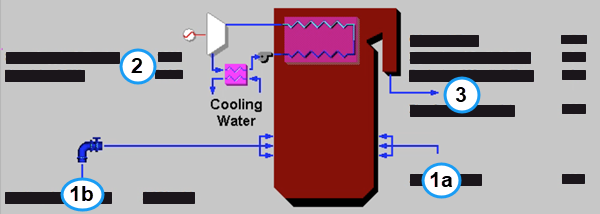
PC: GET RESULTS: CO2 Control: 2. Auxiliary Boiler System: Auxiliary Boiler Diagram
The following values are shown:
•Area 1: Air and Fuel:
•1a: Air In: The mass flow rate of fresh air is provided. This is the stoichiometric amount of air and excess air as specified on the Auxiliary Boiler Performance input screen .
•1b: Auxiliary Gas In: This is the flow rate of natural gas necessary to provide the heat necessary to provide regeneration heat to the sorbent regenerator.
•Area 2: Steam and Power Generation:
•Steam Supply: This is the total steam energy required by the CO2 regenerator. The steam is supplied to the sorbent regenerator.
•Electricity: Low pressure steam generated by the auxiliary boiler may be used to generate electricity in a steam turbine. This electricity supplements that produced by the base plant.
•Area 3: Flue Gas Exiting Aux. Boiler System:
•CO2: This is the emission rate of carbon dioxide from the auxiliary boiler. It is emitted from a secondary stack.
•Equivalent SO2: This is the emission rate of sulfur dioxide from the auxiliary boiler. It is emitted from a secondary stack.
•Equivalent NO2: This is the emission rate of nitrogen dioxide from the auxiliary boiler. It is emitted from a secondary stack.
•Flue Gas Out: This is the mass flow rate of flue gas exiting the auxiliary boiler. It is emitted from a secondary stack.
Copyright © 2022-2026 University of Wyoming. All rights reserved. Visit us at https://www.iecm-online.com/