|
IECM 13.1 User Manual > Modules Included with the IECM > Pulverized Coal (PC) Plant > GET RESULTS > Water Systems > Air Cooled Condenser or 3. Dry Unit > Air Cooled Condenser Diagram |
|
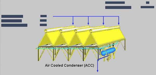
The Air Cooled Condenser Diagram result screen shows the major flows into and out of the air cooled condenser system in all plant types:
PC: GET RESULTS: Water Systems: Air Cooled Condenser: Air Cooled Condenser Diagram
The upper left portion of the diagram shows the exhaust steam entering the air cooled condenser:
•Steam In: The total mass flow rate of the exhaust steam. It depends on the plant size and steam cycle heat rate.
•Steam Temperature: This is temperature of exhaust steam entering the air cooled condensers. It is empirically estimated in terms of the steam turbine back pressure.
•Initial Temp. Diff.: This is the temperature difference between inlet steam and steam of the dry cooling system. This variable significantly affects the performance and cost of the dry cooling system.
The upper right portion of the diagram shows the size of the air cooled condenser:
•Number of Cells: This is the number of cells in the dry cooling system. Each cell has eight heat exchanger bundles in the default. The heat exchanger bundle consists of two-row staggered plat-finned flat tubes.
•Footprint Area: This is the plot area of the dry cooling system. It is a function of initial temperature difference between inlet steam and air and ambient pressure.
Copyright © 2022-2026 University of Wyoming. All rights reserved. Visit us at https://www.iecm-online.com/