|
IECM 13.1 User Manual > Modules Included with the IECM > Integrated Gasification Combined Cycle (IGCC) Plant > GET RESULTS > Air Separation Unit > Air Separation Unit Diagram |
|
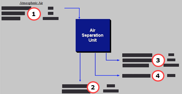
The Air Separation Unit Diagram result screen shows the major flows entering and exiting the air separation unit (ASU). This screen is available in IGCC plants and PC Oxyfuel plants:
IGCC: GET RESULTS: Air Separation Unit: Air Separation Unit Diagram
The following results are displayed:
•Area 1: Atmospheric Air
•Temperature In: Temperature of the atmospheric air entering the air separation unit.
•Air In: Mass flow rate of air entering the air separation unit, based on the atmospheric air temperature and atmospheric pressure.
•Air In: Volumetric flow rate of air entering the air separation unit, based on the atmospheric air temperature and atmospheric pressure.
•Area 2: Nitrogen
•Nitrogen Out: Mass flow rate of the nitrogen exiting the Air Separation Unit.
•Nitrogen Out: Volumetric flow rate of the nitrogen exiting the Air Separation Unit.
•Area 3: Oxidant
•Temperature Out: Temperature of the oxidant exiting the Air Separation Unit.
•Oxidant Out: Mass flow rate of the oxidant exiting the Air Separation Unit.
•Oxidant Out: Volumetric flow rate of the oxidant exiting the Air Separation Unit.
•Area 4: Water
•Water Out: This is the amount of water precipitated out of the main air compressor.
Copyright © 2022-2026 University of Wyoming. All rights reserved. Visit us at https://www.iecm-online.com/