|
IECM 13.1 User Manual > Modules Included with the IECM > Integrated Gasification Combined Cycle (IGCC) Plant > GET RESULTS > Gasifier Area > Shell > Shell Gasifier Diagram |
|
The Shell Gasifier Diagram result screen shows the major flows into and out of the Shell gasifier unit:
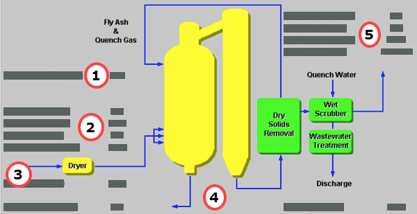
IGCC: GET RESULTS: Gasifier Area: Shell: Shell Gasifier Diagram
Each result is described briefly below:
•Area 1
•Cold Gas Eff.: This is the ratio of the heat contents calculated at room temperature of the syngas fuel output and the coal fuel input. The higher heating value is used here.
•Area 2: Flows Entering the Gasifier
•Temperature In: This is the temperature of the oxidant stream into the gasifier.
•Oxidant In: This is the mass flow of oxidant into the gasifier.
•Steam In: This is the flow rate of steam used for the coal slurry into the Shell entrained-flow gasifier.
•Dried Coal In: This is the flow rate of dry coal into the Shell entrained-flow gasifier. The coal flow rate is on a wet basis.
•Area 3: Coal Entering the Dryer
•Wet Coal: This is the flow rate of wet coal entering the coal dryer.
•Area 4: Slag
•Sluice Water: Slag collected can be removed from the gasifier and disposed by sluicing the slag with water.
•Wet Slag: Slag collected is removed from the gasifier. Sluice water may or may not be used to facilitate its transportation. This is the total slag flow rate leaving the gasifier on a wet basis.
•Area 5: Flows Exiting the Gasifier
•Temperature Out: This is the syngas temperature exiting the Shell entrained-flow gasifier.
•Pressure Out: This is the approximate pressure of the syngas exiting the Shell entrained-flow gasifier.
•Syngas Out: This is the mass flow rate of syngas exiting the Shell entrained-flow gasifier.
•Syngas Out: This is the volumetric flow rate of syngas exiting the Shell entrained-flow gasifier.
Copyright © 2022-2026 University of Wyoming. All rights reserved. Visit us at https://www.iecm-online.com/