|
IECM 13.1 User Manual > Modules Included with the IECM > Integrated Gasification Combined Cycle (IGCC) Plant > GET RESULTS > Sulfur Removal > 1. Sulfinol Sulfur Capture System > Sulfinol Sulfur Capture System Diagram |
|
The Sulfinol Sulfur Capture System Diagram result screen shows the major flows into and out of the Sulfinol sulfur capture system:
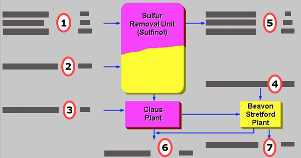
IGCC: GET RESULTS: Sulfur Removal: 1. Sulfinol Sulfur Capture System: Sulfinol Sulfur Capture System Diagram
Each result is described briefly below:
•Area 1: Syngas Entering the Sulfur Removal Unit
•Temperature In: Temperature of the syngas entering the Sulfinol sulfur removal unit.
•Pressure In: Pressure of the syngas entering the Sulfinol sulfur removal unit.
•Syngas In: Flow rate of the syngas entering the Sulfinol sulfur removal unit.
•Area 2: Solvent Entering the Sulfur Removal Unit
•Makeup Solvent: This is the solvent makeup rate into the sulfur removal unit expressed on a continuous basis.
•Area 3: Catalyst Entering the Claus Plant
•Makeup Catalyst: This is the catalyst makeup rate for the Claus plant expressed on a continuous basis.
•Area 4: Catalyst Entering the Beavon-Stretford Plant
•Makeup Catalyst: This is the catalyst makeup rate for the Beavon-Stretford plant expressed on a continuous basis.
•Area 5: Syngas Exiting the Sulfur Removal Unit
•Temperature Out: Temperature of the syngas exiting the Sulfinol sulfur removal unit.
•Pressure Out: Pressure of the syngas exiting the Sulfinol sulfur removal unit.
•Syngas Out: Flow rate of the syngas exiting the Sulfinol sulfur removal unit.
•Area 6: Sulfur
•Sulfur Out: Flow rate of the elemental sulfur collected in both the Claus and Beavon-Stretford plants.
•Area 7: Exhaust Gas
•Flue Gas Out: The exhaust gas from the Beavon-Stretford plant is completely burned and sent to a stack. This is the flow rate of combusted exhaust gases.
Copyright © 2022-2026 University of Wyoming. All rights reserved. Visit us at https://www.iecm-online.com/