|
IECM 13.1 User Manual > Modules Included with the IECM > Pulverized Coal (PC) Plant > GET RESULTS > CO2 Capture, Transport & Storage > 1. Membrane System > Membrane System Diagram > 2-Step w/ Air Sweep |
|
The following diagram is shown for the 2-Step w/ Air Sweep and NETL 2-Step w/ Sweep configurations:
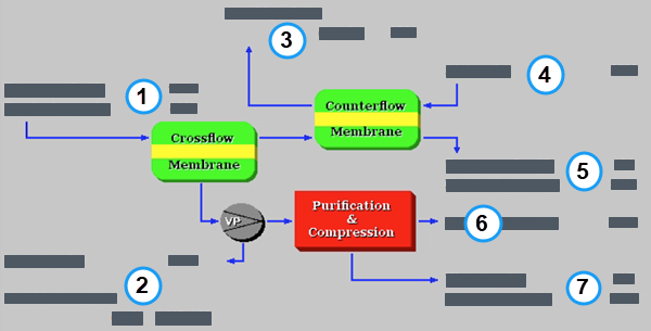
PC: GET RESULTS: CO2 Capture, Transport & Storage: 1. Membrane System: Membrane System Diagram (2-Step w/ Air Sweep)
The following results are shown:
•Area 1:
•Temperature In: This is the temperature of flue gas entering the membrane system.
•Flue Gas In: This is the flow rate of flue gas entering the membrane system.
•Area 2:
•Water: (Only shown for 2-Step w/ Air Sweep) This is the amount of water condensed out from the permeate stream.
•Total Membrane Area: This is the total membrane surface area.
•Area 3:
•Air + CO2 to Boiler: This is the flow rate of combustion air + permeated CO2 recycled to the boiler.
•Area 4:
•Air: This is the flow rate of combustion air used as a sweep gas.
•Area 5:
•Temperature Out: This is the temperature of flue gas exiting the membrane system.
•Flue Gas Out: This is the flow rate of flue gas exiting the membrane system.
•Area 6:
•CO2 Product: This is the amount of CO2 captured.
•Area 7:
•Water: This is the amount of water removed by the CPU.
•Vented Gas: This is the amount of CO2 vented at the CPU.
Copyright © 2022-2026 University of Wyoming. All rights reserved. Visit us at https://www.iecm-online.com/