|
IECM 13.1 User Manual > Modules Included with the IECM > Natural Gas Combined Cycle (NGCC) Plant > GET RESULTS > Power Block > Gas Turbine Diagram |
|
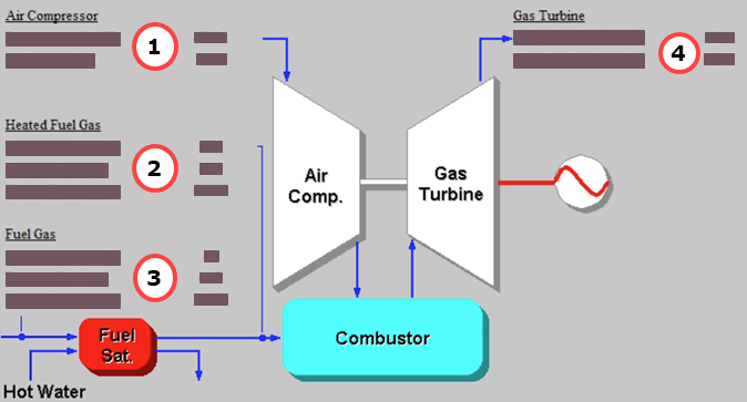
The Gas Turbine Diagram result screen shows the major flows entering and exiting the gas turbine. This screen is available for both the NGCC and IGCC plant types:
IGCC: GET RESULTS: Power Block: Gas Turbine Diagram
The following results are displayed:
•Area 1: Air Entering Compressor:
•Temperature In: Temperature of the atmospheric air entering the air compressor.
•Air In: This is the mass flow rate of the air entering the air compressor.
•Area 2: Heated Syngas Entering Combustor: (only shown for IGCC)
•Temperature In: Temperature of the heated and saturated syngas entering the combustor.
•Pressure In: This is the pressure of the heated and saturated syngas as it enters the combustor.
•Syngas In: This is the mass flow rate of the heated and saturated syngas to the combustor.
•Area 3: Fuel Gas (IGCC) or Natural Gas (NGCC) Entering Combustor:
•Temperature In: Temperature of the fuel gas entering the fuel heater and saturator.
•Pressure In: This is the pressure of the fuel gas as it enters the fuel heater and saturator.
•Syngas In (IGCC) or Natural Gas In (NGCC): This is the mass flow rate of the fuel gas to the fuel heater and saturator (IGCC) or combustor (NGCC).
•Area 4: Flue Gas Exiting Gas Turbine:
•Temperature Out: Temperature of the flue gas exiting the gas turbine.
•Flue Gas Out: This is the mass flow rate of the flue gas exiting the gas turbine.
The fuel heater and saturator, located below Area 3, is only shown for IGCC plants.
Copyright © 2022-2026 University of Wyoming. All rights reserved. Visit us at https://www.iecm-online.com/