|
IECM 13.1 User Manual > Modules Included with the IECM > Natural Gas Combined Cycle (NGCC) Plant > GET RESULTS > Power Block > Steam Turbine Diagram |
|
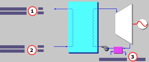
The Steam Turbine Diagram result screen shows the major flows entering and exiting the steam turbine associated with the Heat Recovery Steam Generator (HRSG) system. This screen is available for both the NGCC and IGCC plant types:
IGCC: GET RESULTS: Power Block: Steam Turbine Diagram
The following results are displayed:
•Area 1: Flue Gas Exiting Steam Generator
•Temperature Out: Temperature of the flue gas exiting the HRSG.
•Flue Gas Out: Mass flow rate of the flue gas exiting the HRSG.
•Area 2: Flue Gas Entering Steam Generator
•Temperature In: Temperature of the flue gas entering the HRSG.
•Flue Gas In: Mass flow rate of flue gas entering the HRSG.
•Area 3: Cooling Water: Cooling water required for the HRSG.
Copyright © 2022-2026 University of Wyoming. All rights reserved. Visit us at https://www.iecm-online.com/