|
IECM 14.0 beta User Manual > Modules Included with the IECM > Low-Carbon Hydrogen Production & Transport > GET RESULTS > Reforming Area > Steam Methane Reforming > Pre-Reformer Diagram |
|
The Pre-Reformer Diagram diagram screen shows the major flows into and out of the pre-reformer:
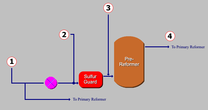
GET RESULTS: Reforming Area: Pre-Reformer Diagram
The following values are shown:
•Area 1:
•Nat Gas: The total amount of natural gas for feedstock and fuel consumed by the hydrogen production plant.
•Temperature: The temperature of the natural gas for feedstock and fuel consumed by the hydrogen production plant.
•Pressure: The pressure of the natural gas for feedstock and fuel consumed by the hydrogen production plant.
•Area 2:
•Feedstock In: The amount of natural gas as feedstock entering the sulfur guard.
•Temperature: The temperature of the natural gas as feedstock entering the sulfur guard.
•Pressure: The pressure of the natural gas as feedstock entering the sulfur guard.
•Area 3:
•Steam: The amount of steam entering the pre-reformer reactor.
•Area 4:
•Outlet: The amount of gas exiting the pre-reformer reactor.
•Temperature: The temperature of the gas exiting the pre-reformer reactor.
•Pressure: The pressure of the gas exiting the pre-reformer reactor.
Copyright © 2022-2026 University of Wyoming. All rights reserved. Visit us at https://www.iecm-online.com/