|
IECM 14.0 beta User Manual > Modules Included with the IECM > Low-Carbon Hydrogen Production & Transport > GET RESULTS > Flue Gas CO2 Capture > MEA > CO2 Compressor Diagram |
|
The CO2 Compressor Diagram diagram screen shows the major flows into and out of the CO2 compressor:
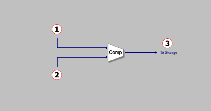
GET RESULTS: Flue Gas CO2 Capture: CO2 Compressor Diagram
The following values are shown:
•Area 1:
•CO2 Captured from MDEA: The amount of CO2 captured by the CO2 adsorption unit using MDEA.
•Area 2:
•CO2 Captured from MEA: The amount of CO2 captured by the CO2 adsorption unit using MEA.
•Area 3:
•CO2 Product: The total amount of CO2 captured (Area 1 + Area 2).
•Pressure: The pressure of the captured CO2.
Copyright © 2022-2026 University of Wyoming. All rights reserved. Visit us at https://www.iecm-online.com/