|
IECM 14.0 beta User Manual > Modules Included with the IECM > Low-Carbon Hydrogen Production & Transport > GET RESULTS > Transport > Pipeline > Pipeline Diagram |
|
The Pipeline Diagram diagram screen shows the major flows into and out of the pipeline transport system:
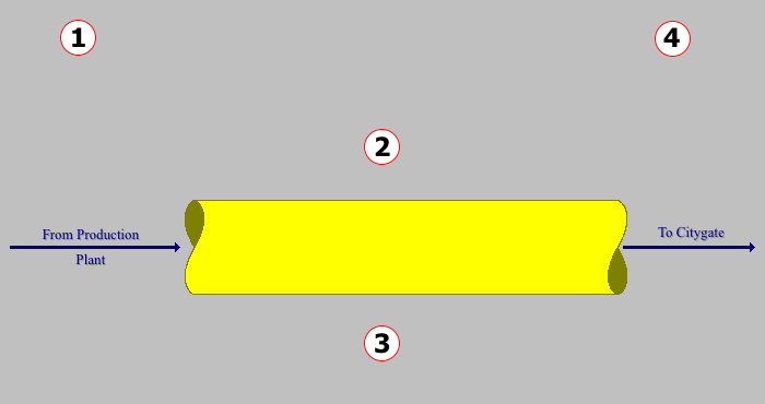
GET RESULTS: Transport: Pipeline Diagram
The following values are shown:
•Area 1: From Plant
•Pressure In: This is the pressure of the H2 from the plant into the pipeline.
•Temp In: This is the inlet temperature of the gas in the pipeline.
•H2 Stream In: This is the flow of the H2 from the plant into the pipeline at operating conditions.
•Area 2: To H2 Transport System
•H2 Flow Rate: This is the flow of the H2 at standard conditions.
•Number of Comp Stations: This is the number of compressors used (if any).
•Compressor Power: This shows the total compression power required along the route.
•Comp Interval: This is the compressor placement interval.
•Area 3: Pipeline Characteristics
•Pipe Size: This is the outer diameter of the pipe.
•Pipe Schedule: This is the pipeline schedule as per market.
•Area 4: To Citygate
•Pressure Out: This is the pressure of the H2 when it reaches the city gate.
•Temp Out: This is the temperature of the H2 when it reaches the city gate.
•H2 Stream Out: This is the flow of the H2 from the pipeline to the city gate at operating conditions.
Copyright © 2022-2026 University of Wyoming. All rights reserved. Visit us at https://www.iecm-online.com/