|
IECM 13.1 User Manual > Modules Included with the IECM > Pulverized Coal (PC) Plant > GET RESULTS > Water Systems > 2. Hybrid Cooling System > Hybrid Cooling System Diagram |
|
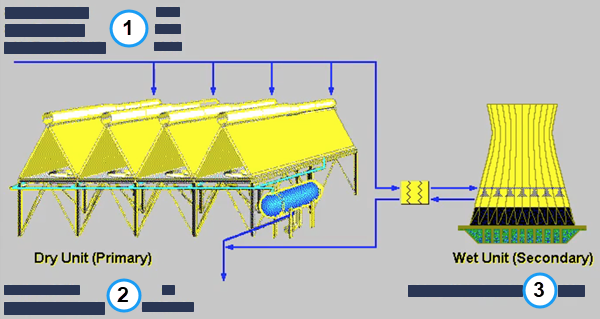
The Hybrid Cooling System Diagram result screen shows a summary of the hybrid cooling system in all plant types:
PC: GET RESULTS: Water Systems: Hybrid Cooling System: Hybrid Cooling System Diagram
The upper left corner (area 1) shows the exhaust steam entering the hybrid cooling system. These results are also found on the Air Cooled Condenser Diagram and are described there:
•Steam In
•Steam Temp.
•Initial Temp. Diff.
The lower left corner (area 2) shows the size of the dry unit. These results are also found on the Air Cooled Condenser Diagram and are described there:
•Number of Cells
•Footprint Area
The lower right corner (area 3) shows the makeup water required for the wet unit:
•Makeup Water: This is amount of makeup water required annually by the wet unit. Changing the Result Time Period will not affect this result, as the standard unit conversion does not work for this value. The hourly makeup water requirement while the unit is in operation is shown on the Cooling Tower Diagram, along with other related results.
Copyright © 2022-2026 University of Wyoming. All rights reserved. Visit us at https://www.iecm-online.com/