|
IECM 14.0 beta User Manual > Modules Included with the IECM > Low-Carbon Hydrogen Production & Transport > GET RESULTS > Water System > Makeup Water Diagram |
|
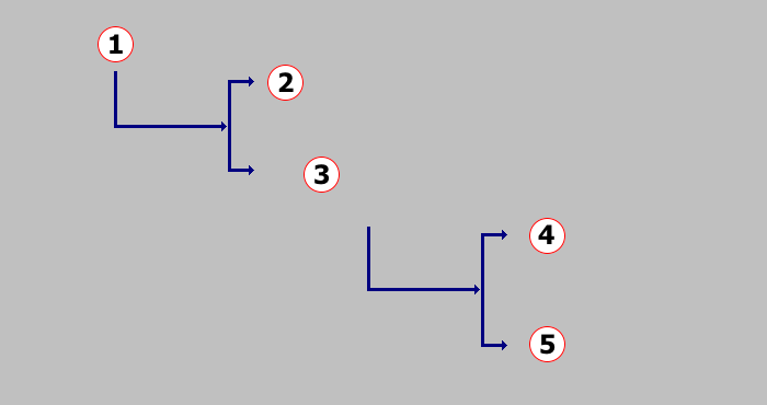
The Makeup Water Diagram diagram screen shows the makeup water for hydrogen production:
GET RESULTS: Water System: Makeup Water Diagram
The following values are shown:
•Area 1:
•Plant Makeup Water: This is the total amount of makeup water required by the plant. This is demineralized makeup water.
•Area 2:
•Cooling Makeup Water: This is the amount of makeup water for the cooling system. For the wet cooling tower, the makeup water is required to offset the evaporation, blowdown, and drift losses.
•Area 3:
•Process Makeup Water: This is the amount of makeup water required for the three major process areas. This represents the net process makeup water consumption.
•Area 4: Makeup
•Reforming: This is the amount of water consumed for steam generation. Steam is required for natural gas reforming.
•Syngas Cleanup: This includes water associated with the wash column operation and solvent makeup requirements, which depend on the MDEA solvent makeup rate during syngas cleanup.
•Flue Gas Capture: This includes water associated with the wash column operation and solvent makeup requirements, which depend on the MEA solvent makeup rate during flue gas CO2 capture.
•Area 5: Recycle for Reforming
•Syngas Cleanup: This is the amount of water recovered and recycled during the MDEA regeneration process.
•Flue Gas Capture: This is the amount of water recovered and recycled during the MEA regeneration process.
Copyright © 2022-2026 University of Wyoming. All rights reserved. Visit us at https://www.iecm-online.com/