
Dr. Duane S. Ellifrit
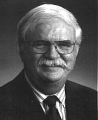 |
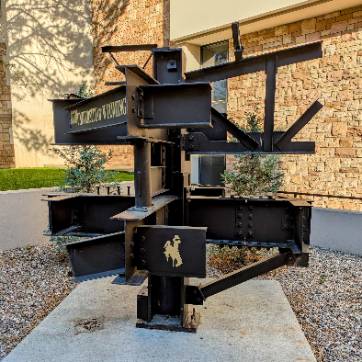
The Crom Professor of Structural Design at the University of Florida, Ellifritt brings impressive credentials to the University of Wyoming. Prior to his appointment at the University of Florida, he was Director of Engineering and Research for the Metal Building Manufacturers Association, and had spent five years teaching civil engineering courses at Oklahoma State University. Those familiar with the Engineering Building will remember the appearance in early 1997 of the orange steel structure to the east of the building. Designed by Ellifritt, the structure is intended as a visual lesson to students who have never been around a construction site where a steel structure is being erected. Visualizing a three-dimensional detail connection from two-dimensional figures in books and on blackboards is obviously a problem for many students, and Ellifritt's teaching structure is a step in solving that problem. The following is a description of some of the connections on the orange steel structure. The welds presented are not intended to represent all possible connections. There are other connection types that are equally valid. There are many variables like bolts vs. welds, shop vs. field attachment among others that appear within a single connection. This shows some common types of connections used in steel construction today. |
Connections
The information on this page comes from a booklet entitled Connecting Steel Members A Teaching Guide written by Dr. Duane S. Ellifritt.
Zalk Josephs Fabricators, a specialist in the complex fabrication of structural steel framing, modified Dr. Ellifrit's original design to produce the following structure.
Click through the accordion control to view a close up of the different connections.
This connection is the end plate moment connection. It is made by shop-welding a plate to the end of a beam and field-bolting it to a column or to another beam. The four bolts around the tension flange transmit the flange force into the column. Additional bolts may be needed in deeper sections. A bolt may also be added near the neutral axis of the beam to prevent gaps between the plates.
This is a double-sided shear connection. A dangerous situation can arise when filler beams frame into opposite sides of a girder and share the same holes in the girder web. One way to avoid this is to offset the beams. Another solution is shown here; simply add an extra bolt beyond those needed to carry the shear. This extra bolt, at the bottom of the connection, goes through only one set of double angles and can be used to hold the right-hand beam temporarily in position until the left-hand beam is fitted up, then all the bolt-holes can be filled.
This connection is an end plate shear connection as opposed to an end plate moment connection. The plate in this connection is welded to the web only. One disadvantage of this connection is that a plane perpendicular to the web is not automatically assured as it would be if the plate covered the flanges as well.
This is a bolted top shear connection. A top and seat connection uses fewer field bolts and has the advantage of having a place to set the beam during erection. This presumes that the seat angle is attached to the column flange prior to setting the beam. In this example it is shown bolted, but it could as easily have been shop-welded. All the shear in this connection is carried by the seat angle; that is why it is heavier than the top angle, which is only there for torsional stability.
Top and seated connections may be used on column flanges, column webs or girder webs. In the case of large shear loads, a stiffener may be used beneath the seat.
This is a skewed shear connection. Members do not always meet at right angles. The easiest way to make this connection is to weld a bent plate to the web of the smaller member, in this case a channel, then field-bold it to the web of the larger section.
A round pipe column sits atop a wide flange and is fastened with a rectangular end plate having four bolts. Even though all the bolts lie outside the round section, this is generally designed as a pinned connection. The column delivers a concentrated load to the beam and a bearing stiffener is used on the web.
This is a double web angle shear connection, bolted to both the beam and girder webs. The angles would be shop-bolted to the beam, then field bolted to the girder web.
Note that the bolts are staggered to facilitate the use of an impact wrench under tight clearance conditions. If there is plenty of clearance to access the bolt heads it is not necessary to stagger them as shown here. Also note that the beam is coped on both flanges. This condition requires additional design checks. The angles used in this connection are generally thin enough to deform under eccentric load and cause the connection to behave as a pure shear connection.
This is a beam splice moment connection. The flange plates and bolots in this beam splice must be capable of transferring all the flange force from one side to the other. The web plate and bolts may help to resist moment, but their primary function is to transfer shear across the splice.
This moment connection has flange plates on the outside only. In some connections it may be necessary to have plates inside the flanges as well.
A typical column splice is shown here. Plates are shop-welded to the lower column, then field-bolted to the smaller upper column. If the columns are of the same nominal depth but differing flange thickness, then a filler plate or shim must be used.
This is a field-welded moment connection. Full-penetration welds are required at the beam flanges. The web plate is shop-welded to the column flange and is there to locate the correct position of the beam and hold it until it can be welded. Backing bars are usually required beneath the full-pen welds and are sometimes left in place. Access holes are burned into the beam web to facilitate field welding.
A weld around the shear tab to the beam web can be used to increase shear capacity.
If a moment connection is required at a column base, it is essential to get the anchor bolts outside the flanges. If the weld is not sufficient to transmit the flange force into the base plate, additional weld may be obtained by welding vertical plates or angles to the flange and lengthening the anchor bolts.
Shown here is an example of a type of shear connector that causes the steel beam and the concrete slab to act as an integral unit. These are headed studs and the beam and slab make what is called a composite beam. These studs are electrical resistance-welded to the beam with a special tool, either in the shop or in the field.
This is a field bolted moment connection to a column web. The flange plates are welded to the column in the shop and are made to fill the entire space between the column flanges. In this way they can serve as web stiffeners in addition to transmitting the beam flange force into the column. The beam shear is assumed to be carried by the web bolts.
Erection of this connection is simplified by extending the horizontal flange plates and the vertical web plate so that all bolting takes place outside the flanges of the column.
The truss is shop-welded of angles and gusset plates. The top and bottom chords are double angles, while the web members are single angles.
Because channels are usually lightly loaded, the attachment of a channel beam web may be make by use of a single angle, shop-welded to the beam web, then field-bolted to the channel.
An all-welded column splice. The web plate is shop-welded to the lower column, then the upper column is lowered into the connection and field-welded. The web bolts are just for fit-up and erection.

The University of Wyoming has earned its Research Level 1 (R1) status from the Carnegie Classification of Institutions of Higher Education, placing Wyoming's only four-year university with the top research universities in the United States.