Co-Location Technical Details
Co-Location Racks
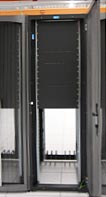
The ITC Data Center uses a custom configured, Chatsworth Products, Inc. (CPI) TeraframeTM cabinet. This document includes information you’ll need to determine if your equipment is suitable for installation and use in the cabinet.
Clients are responsible for installing their equipment in these cabinets, and providing the rack/rail kits and hardware required to do so. Data Center staff is available to answer questions, provide work carts, step stools, and general assistance.
Will It Fit? (Dimensions)
The cabinets are designed to provide front and rear support for 19” width EIA rack mount equipment.
This 19-inch racking standard (EIA 310-D, IEC 60297 and DIN 41494 SC48D) is well recognized, and manufacturers make most of their products to conform. Conforming equipment front panel is 19 inches (480 mm) wide, including edges or ears that protrude on each side to allow the module to be fastened to the rack frame with screws.
The height of rack mounted equipment is also standardized, as multiples of 1.75 inches (44.45 mm), called a "rack unit", "rack mount unit", "RU", "RMU", or "U".
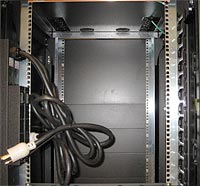
The cabinet uses two pairs of vertical mounting rails in the cabinet body - two in the front, two in the back - forming a four post rectangle.
 The rail mount kit will typically include two pieces that mount to the
cabinet vertical rails (one front to back on the left side, the other
front to back on the right side of the cabinet) and either posts or
runners on the left and right sides of the equipment. The equipment then
slides in (much like a kitchen drawer), so the equipment can be
supported inside the cabinet, or extended forward, out the front of the
cabinet for maintenance.
The rail mount kit will typically include two pieces that mount to the
cabinet vertical rails (one front to back on the left side, the other
front to back on the right side of the cabinet) and either posts or
runners on the left and right sides of the equipment. The equipment then
slides in (much like a kitchen drawer), so the equipment can be
supported inside the cabinet, or extended forward, out the front of the
cabinet for maintenance.
The cabinets have a 29” rail depth. This is the distance from the front vertical rail mounting surface, to the back vertical rail mounting surface. Your rail kit must be able to attach at this depth. Most kits adjust to fit a range of depths, and 29” depth is in the normal range – it’s unlikely a rail kit would not adapt to this depth.
 The cabinets have a 38.4” frame depth, and the vertical rails are offset
approx. 1.7” in the front, and 7” in the back. This matters because the
equipment you install will usually need some small additional clearance
beyond the front rail, and in some cases, clearance beyond the rear
rail. The critical distance here is the overall depth of your equipment
(if its deeper than about 38”, it won’t fit in the cabinet) and the
overhang, front and back, in relation to the vertical rails – it can
hang out about 2.5” past the front vertical rail, and no more than 7” in
the back (include the distance for power cord and cable connections that
protrude further back from your equipment. This allows the front and
rear cabinet doors to close (a requirement). Again, most rack mountable
equipment should fit, with most exceptions being for some of the very
large rack mountable equipment.
The cabinets have a 38.4” frame depth, and the vertical rails are offset
approx. 1.7” in the front, and 7” in the back. This matters because the
equipment you install will usually need some small additional clearance
beyond the front rail, and in some cases, clearance beyond the rear
rail. The critical distance here is the overall depth of your equipment
(if its deeper than about 38”, it won’t fit in the cabinet) and the
overhang, front and back, in relation to the vertical rails – it can
hang out about 2.5” past the front vertical rail, and no more than 7” in
the back (include the distance for power cord and cable connections that
protrude further back from your equipment. This allows the front and
rear cabinet doors to close (a requirement). Again, most rack mountable
equipment should fit, with most exceptions being for some of the very
large rack mountable equipment.
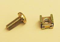
Fastener Scheme
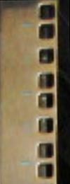 The cabinet vertical mounting rails provide 45 RU’s of mounting height,
and use a square punch mounting scheme. This requires Cage Nuts (we
stock M6 size, see photo below) with screws for each mount point.
Rack/rail kits usually come with cage nuts and matching screws. They
also usually indicate where to put the cage nuts, and how many are
needed.
The cabinet vertical mounting rails provide 45 RU’s of mounting height,
and use a square punch mounting scheme. This requires Cage Nuts (we
stock M6 size, see photo below) with screws for each mount point.
Rack/rail kits usually come with cage nuts and matching screws. They
also usually indicate where to put the cage nuts, and how many are
needed.
An RU is a standard used to indicate the racked height of equipment. One RU is 1.75”. Equipment manufacturers list equipment height in RU’s. For example, a 1 RU unit is 1.75” tall, and a 5 RU unit is 8.75” tall. Actually, vendors make their heights just slightly less than the full RU height, so there is clearance room between mounted systems.
 For
mounting, each RMU has three punched squares (for cage nuts), spaced
.625” center to center, but the spacing from the two outside squares to
adjacent RU squares (above/below) is only .5”, center to center. So,
this means the equipment mounting must align with the RU markings on the
vertical rails, in order for the equipment mounts to line up with the
cage nuts. Our cabinet vertical rails have blue markings, numbered from
1 (bottom) to 45 (top), to make it easy to assure your equipment is
mounted to stop and start at the edge of the RU’s.
For
mounting, each RMU has three punched squares (for cage nuts), spaced
.625” center to center, but the spacing from the two outside squares to
adjacent RU squares (above/below) is only .5”, center to center. So,
this means the equipment mounting must align with the RU markings on the
vertical rails, in order for the equipment mounts to line up with the
cage nuts. Our cabinet vertical rails have blue markings, numbered from
1 (bottom) to 45 (top), to make it easy to assure your equipment is
mounted to stop and start at the edge of the RU’s.
If you are unfamiliar with RU’s and rack mounting, this may seem a bit of a pain – but your equipment vendor will be familiar with these concepts, and the Data Center Operations staff can help answer questions as well.
Once your equipment is installed, Data Center staff will provide filler panels to cover any front side openings above, below or between the equipment. Filler panels isolate the front cold aisle from the rear hot aisle.
Electrical
The Data Center is standardized on 208 VAC power. Your equipment should run off of 208 VAC. Each cabinet has two vertically mounted PDU’s, where you plug in your equipment power cords. Power cords should connect to one of these receptacle types. The standard 110 wall plug you use with office/home wall outlets will not work.
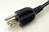
Your familiar NEMA 5-15P won't work
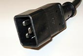
C20 will work (plugs into C19’s)
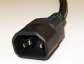
C14 will work (plugs in to C13’s)
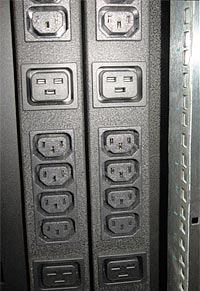
PDU's, with C13 and C19 receptacles
Power drops to the cabinet PDU’s come from separate distribution paths
and UPS units. If your equipment uses multiple power supplies in a 2N or
N+1 configuration, you will be able to connect the supplies to separate
distributions by connecting to the two PDU’s.
Other power configurations may be possible, as exceptions, and at an additional cost, such as 3 phase 120 VAC. Consult with the Data Center Manager for such configurations.
PDU’s include 2 separate breaker protected circuits, 20 amps each (de-rated to 16 amps). This theoretically provides well over 10KW of power to the rack, although such a load may exceed cooling requirements. Note that current (in amps) is metered, by LED readout, at each PDU. This allows DC operations and clients to see how much electrical load is being produced by the equipment plugged in to the PDU.
Cooling
The Data Center cabinets are designed for equipment with front to back air cooling. Cold air is delivered from perforated floor tiles in front of the cabinet. Equipment fans pull the cool air in at the front, and discharge hot air out the back. The Data Center cabinet layout is designed in a hot aisle/cold aisle configuration, with equipment rows aligned “back to back”. Your equipment should be designed for front to back air cooling. This is the common design in rack mounted equipment, but some equipment (e.g., older storage arrays, network switches) uses a side to side air cooling design, and would not be suitable for our cabinets.
The average cabinet should produce no more than 2.5 – 3 KW of IT load, to match the overall capacity of the Data Center, but some cabinets will produce more. If your installed equipment represents a large heat load, there may be special requirements, and costs, to prepare the data center for your equipment. A good rule of thumb is to count the CPU’s, as they are the primary heat producers. If your equipment includes many CPU’s in a small package (e.g. a blade server or cabinet based computing cluster) you’re more likely to require some cabinet upgrades to manage cooling. There are limits to how large/dense of a heat load the Data Center can handle. If you are considering such devices, consult with the Data Center Manager to determine if your equipment is suitable for co-location.
Cable Management
At the back of the cabinet, there are a couple of cable management devices installed:
- A vertical cable manager on the right (as you look in from the back). Use this to run network copper, fiber and KVM cabling up and down the rack.
- There are two horizontal cable managers, across RU’s 1 – 2, and RU’s 30-31, for routing power cords across the unit (PDU’s are on the left side).
- Also on the left side, behind the vertical cable manager, there is a power cord vertical management run, but it’s a bit hard to access and use – it’s not required that you run power cables in this area.