
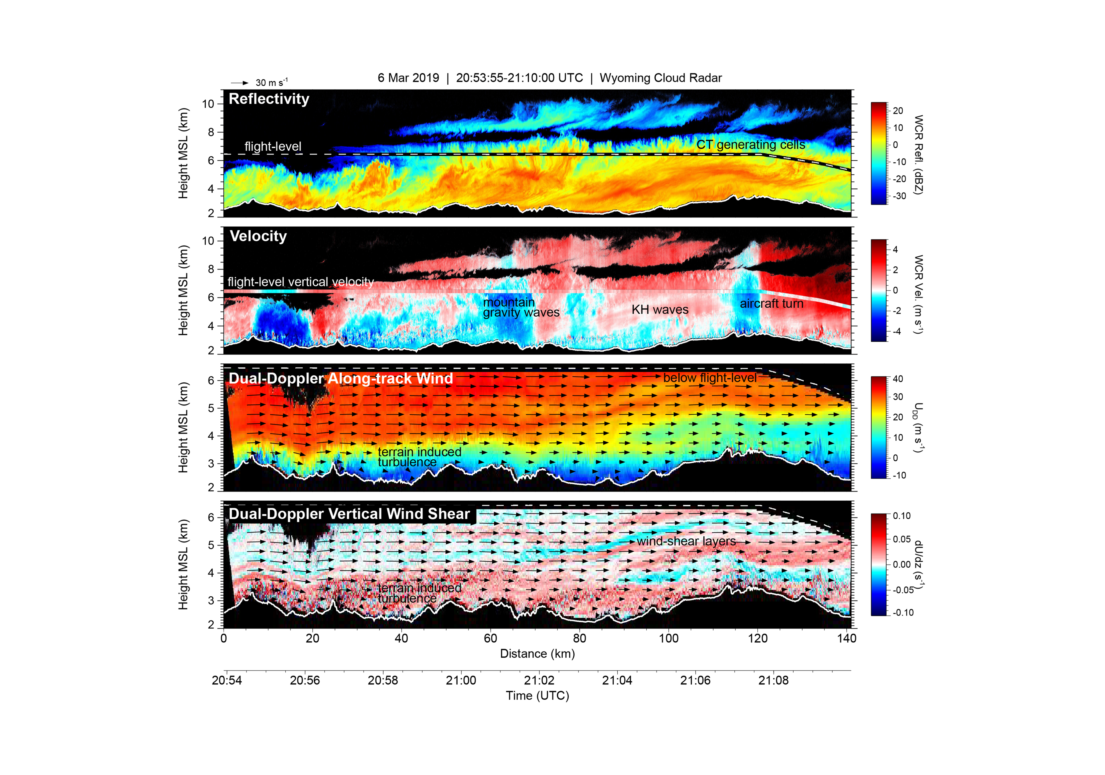
WCR is used in operations where it is desired to describe weather events such as clouds, precipitation, and aerosol, and to provide specific information of these targets. The typical antenna configuration of the WCR observes a plane, or vertical curtain, along the flight track of the aircraft. By simultaneously using two antennas in this plane (e.g. one in the vertical plane and one forward of vertical), dual-Doppler analysis is possible. Coupled with the in situ observations of hydrometeors and air motions from the same aircraft these data yield unique information for analysis of cloud and precipitation processes.
Data Products
During deployment quicklooks of reflectivity and Doppler velocity are provided in PDF files. A preliminary processed data of the standard radar products in netCDF files are made available. Typically, both are made available within 24 hours after a flight. Standard data products after quality control includes:
- Co-polarized reflectivity
- Cross-polarized reflectivity (if applicable)
- Mean Doppler velocity (radial velocity along each active antenna beam corrected for aircraft motion)
- 3-dimensional spatial reference (radar platform location and speed, and beam pointing directions
Level-1 data contains products in their natural grid (time x range) without any averaging, thresholding, or masking.
Level-2 data is projected into a vertical plane using a regular grid with dimensions of time and altitude. They are averaged using an integer number of profiles and range gates then thresholded to remove most of the noise. If up and down antennas are opperated simultaneously, a second "up-down" file is provided that contains merged profile data like what is shown to the left.
* Dual-Doppler wind is not a standard product in L1 or L2 data but it can be generated during scientific collaboration with UW.
WCR Projects and QuicklooksRadar Specifications
Depending on the antenna configuration, WCR can be operated in various single- and multi-beam configurations. One of the radar's advantages is that it depicts reflectivity and velocity fields at high spatial resolution - on the order of tens of meters.
| Specification | WCR | KPR |
| Transmit Frequency | 94.94 GHz | 35.64 GHz (center frequency) |
| Amplifier | Extended Interaction Klystron (EIK) | Solid State Power Amplifier (SSPA) |
| Peak power / Duty Cycle | 1.6 kW / 1% | 10 W / 10 - 46% |
| Pulse Length | 100, 200, 250 ns | 200, 400, 500 ns (pulse, x10 for chirp) |
| Pulse Repitition Frequency (PRF) | 1 - 20 kHz | 1 - 20 kHz |
| Polarization | Single linear or Dual linear (H & V) | Single linear |
| Transmitted pulse packet | 1 - 12 sequenced linearly polarized pulses | 3 linearly polarized pulses |
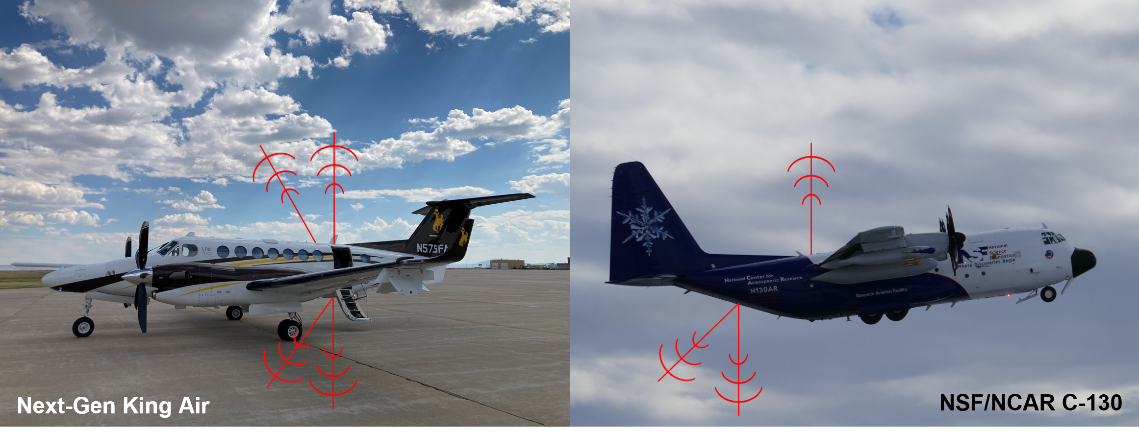
| Number of Antennas per Platform | UW King Air: Up to 4 antennas NCAR C-130: 3 antennas |
vertically profiling antennas (up and down) |
| Antenna Types |
|
Slotted waveguide |
| Antenna Beamwidths |
|
2.1° |
| Antenna Configuration (UWKA) |
|
Zenith and Nadir |
| Antenna Configuration (C-130) |
|
Zenith and Nadir |
| Maximum Range | 6 - 10 km (typical) | 6 - 10 km (typical) |
| Along-beam Sampling | 7.5 - 37.5 m | 15.0 - 37.5 m |
| First Range Gate | 111 m | 127 m (pulse), 546 m (chirp), 34 m (qpc) |
| Maximum (Nyquist) Velocity | 14.3 m/s (typical) | 41.5 m/s (typical) |
| Typical Dwell-time (Along-track Sampling) | 49.5 ms (4 - 5 m) | 150 ms (12 - 15 m) |
| Minimum Detectable Signal (MDS) @ 1 km | -35 dBz (typical) | -2 dBz (typical pulse) & -14 dBz (typical chirp) |
The University of Wyoming has earned its Research Level 1 (R1) status from the Carnegie Classification of Institutions of Higher Education, placing Wyoming's only four-year university with the top research universities in the United States.