
Department of Electrical Engineering and Computer Science
College of Engineering and Physical Sciences

About Our Department
The Electrical Engineering and Computer Science (EECS) Department is committed to excellence in teaching, research, and service. Distinguished faculty conduct world-class research and their instruction is recognized via numerous teaching awards. Rigorous instruction, small class sizes, and extremely competitive tuition guarantee an accessible, challenging, and rewarding experience in EECS.
EECS offers undergraduate degrees in Electrical Engineering, Computer Engineering, and Computer Science. These programs include concentrations in big data, business applications, bio-engineering, and a K-12 endorsement and cybersecurity certificate. QuickStart programs allow top students to earn a MS and BS in a total of five years.
EECS offers MS and PhD programs in Electrical Engineering and in Computer Science. Areas of expertise in EE include: Bio-engineering, Controls, Electrical Energy Systems, Internet of Things, Robotics, Signal Processing and Computer Networks. Areas of expertise in CS include artificial intelligence, computational complexity, cybersecurity, formal methods and theorem proving, Human-centered computing and interactions, 3D User interfaces and graphics.
At the Department of Electrical Engineering and Computer Science, we are proud to be a part of this college and University while helping mold the next generation of computer and electrical engineers and scientists.
Department of Electrical Engineering and Computer Science Resources
Undergraduate
Learn more about what it take to become an undergraduate student in the Department of Electrical Engineering and Computer Science and what resources are available to you!
Undergrad InformationGraduate
Interested in a higher degree in computer science or electrical engineering? View your options and see if grad school is the right choice for you.
Research
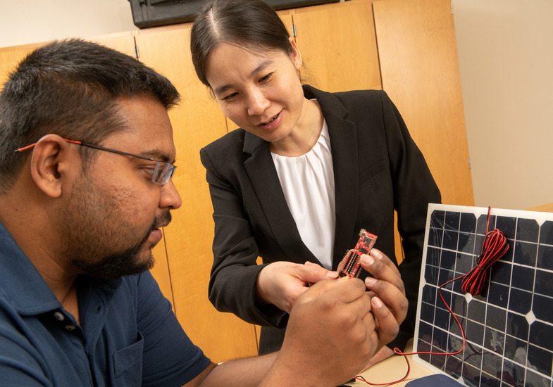
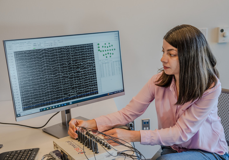
In our department, we pride ourselves in our research in modern power grid date analysis and modeling, AI/ML and HPC, visual and interactive computer and cybersecurity.
Alumni
Are you an alumni of the Department of Electrical Engineering and Compute Science? Get connected with other alumni, view alumni resources and see alumni news!
EECS Colloquia
Interested in electrical and computer engineering or want to dive deeper into computer science? Take a look at the EECS Colloquium Series and attend an event!
Careers in EECS
EECS faculty train the next generation of engineers, researchers, and scientists. Their blend of funded research and industry experience bridges the gap between theory and practice, preparing students with essential skills for top employers.
Faculty and Staff
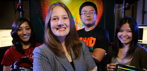
Home to top professors, scholars and researchers in the electrical engineering and computer science field, the people in the Department of Electrical Engineering and Computer Science provide an exceptional education to everyone that walks through their doors. From robotics to lasers and databases to cybersecurity, our department dives deep into their research topics and hones in on their craft to give you the most up-to-date education in the ever-evolving technological world.

ABET Accredited
The College of Engineering and Physical Sciences is accredited by the Engineering Accreditation Commission of ABET. Since the Department of Electrical Engineering and Computer Science falls under that umbrella, you know you're getting a top-tier education in our department!
Read more about the Department's Student Learning Outcomes and Program Educational Objectives.
Department of Electrical Engineering and Computer Science News
Walker Named Head of UW Department of Electrical Engineering and Computer Science
September 9, 2024
After a competitive search, the University of Wyoming College of Engineering and Physical Sciences has selected Ian Walker to...
Read the StoryAverage Entry Level Salaries
If you're interested in applying to the University of Wyoming and beginning your journey with the Department of Electrical Engineering and Computer Science, you can apply today!
Come visit our beautiful campus and check out our state-of-the-art engineering and computing facilities!
Contact us with any questions! We're happy to talk to you.
The College of Engineering and Physical Sciences is home to many amazing departments, people, experiential learning opportunities and more. Check it out!
Your gift matters! If you're interested in giving to the Department of Electrical Engineering and Computer Science, click the button below and be sure to select "Electrical Engineering & Computer Science" on the form.
DonateThe University of Wyoming has earned its Research Level 1 (R1) status from the Carnegie Classification of Institutions of Higher Education, placing Wyoming's only four-year university with the top research universities in the United States.